T6: Electronic & Electrical Components
4 of 35 exam questions come from this section.
Read-aloud isn’t available in this browser. Try Chrome, Edge, or Safari, or read along below.
Imagine electricity is like water moving through pipes. Some water gets pushed hard, and some of it actually flows. The push is called voltage, and the amount that flows is called current. A radio is stuffed with tiny parts, and each one does just one simple thing to that flowing "water." Some parts slow it down on purpose. Some store a little of it for later, like a bucket. Some let it flow only one way, like a one-way gate. Some act like faucets that turn the flow on and off. And some are safety parts that break first so nothing else breaks. This whole lesson is just a tour of those parts, one at a time, using pictures you already know from everyday life.
Here is the good news: you will not have to build anything, and there is no math in this lesson at all. For each part you only need to remember two simple things: (1) what the part does (its job), and (2) what its little drawing — called its "symbol" — looks like. A "symbol" is just a quick doodle that stands for a part, the way a drawing of a fork-and-knife on a sign means "restaurant."
That second thing — the symbols — matters because engineers almost never draw real photos of a circuit. Instead they draw a kind of treasure map called a schematic (say "skuh-MAT-ik"). A schematic uses one simple symbol for every part and shows how all the parts hook together. Some exam questions show you a picture labeled Figure T-1, Figure T-2, or Figure T-3 and point at a numbered symbol, asking "what is this part?" This course automatically pops the correct figure up right next to the question, so once you can recognize a handful of symbols, those turn into some of the easiest points on the whole test. About 4 of the 35 questions on the real exam come from this group, called T6.
Why this matters
Knowing the basic parts inside your radio pays off in real, everyday ways. When you read the manual or a help post online, words like "capacitor," "fuse," "transistor," or "regulator" stop being scary and start making plain sense. If a fuse blows or a power cable goes bad, you can spot the problem and fix it yourself instead of paying someone or tossing the radio in the trash. And when something acts strange, understanding what each part does helps you guess why it's misbehaving — for example, a dim "power on" light usually points to a power or LED issue, not a broken antenna. You don't have to become an engineer; just knowing a small handful of parts turns your radio from a scary mystery box into something you actually understand. On top of that, these are some of the easiest, most predictable points on the exam, so a little time here is worth a lot of correct answers on test day.
A helpful way to picture it
Almost every part in this lesson has a plain household twin. Picture these and you've basically got the lesson:
- Resistor = a kink in a garden hose that slows the water down on purpose, so less flows through.
- Capacitor = a small rechargeable bucket that fills up with energy (in an electric field) and pours it back out later.
- Inductor = a heavy spinning flywheel (a coil of wire) that resists sudden changes and stores energy in a magnetic field.
- Diode = a one-way gate or turnstile — flow goes through one direction only and is blocked the other way.
- Transistor = a big faucet that a tiny hand can turn — a small signal controls a much bigger flow, so it can switch or amplify.
- Fuse = a deliberate weak link in a chain that snaps first to save everything attached to it.
- Transformer = a set of gears that trades voltage for current (works only on AC).
If you can picture these everyday objects, you already understand most of what these parts actually do.
The details
T6A — Resistors, capacitors, inductors, fuses, switches, and batteries
Keep picturing electricity as water moving through pipes. Voltage is how hard the water is pushed, and current is how much water actually flows past a point. Almost every part in this section does something to that "water." Let's meet them one at a time, the easy way: an everyday picture first, then the real name in bold, then exactly what the exam asks about it.
Resistor — a kink in the hose
A resistor (say "ree-ZIS-ter") is like a pinch or a kink in a garden hose. When you squeeze the hose, it gets harder for the water to push through, so less water flows. A resistor does the same thing to electric current: it makes the flow harder, so less current gets through. In proper words, a resistor opposes (fights against) the flow of current. That is its entire job — to slow current down on purpose. So if a question asks "what component opposes the flow of current in a DC circuit?", the answer is the resistor. ("DC" just means current that flows steadily one way, like a river — we'll meet it again later.) A plain resistor is called "fixed," which means it always pinches by the same amount and you can't change it.
Some resistors are variable, which means you can change how hard they pinch by turning a knob. The most famous variable resistor is the potentiometer (say "po-TEN-shee-AH-meter," but everybody just says "pot"). When you turn the volume knob on a radio, you are almost always turning a potentiometer. So the answer to "what part is often used as an adjustable volume control?" is a potentiometer. And the thing it actually changes is the amount of pinch, which we call resistance. So the answer to "what does a potentiometer control?" is resistance. (It does NOT control voltage, capacitance, or "field strength" — just resistance. That trips a lot of people up.)
Capacitor — a tiny rechargeable bucket
A capacitor (say "kuh-PASS-it-ter") is like a little bucket that can fill up with electrical energy and then pour it back out later. It stores energy in an electric field. An "electric field" sounds fancy, but it just means the invisible push that builds up between two charged surfaces sitting near each other — like the static crackle you feel when you rub a balloon on your hair. So the answer to "what part stores energy in an electric field?" is the capacitor.
Now, what is a capacitor made of? Inside, it is built from two metal surfaces with an insulator squeezed between them. An insulator is a material that does NOT let electricity flow through it, like the rubber coating on a wire or the air gap between two plates. The electric charge piles up on the two metal surfaces but it can't jump across the insulator in the middle, so it just waits there, stored, like water held in a bucket. That is why the answer to "what part consists of conductive surfaces separated by an insulator?" is also the capacitor. (Notice that question is just describing how the bucket is built.) Like resistors, some capacitors are made variable so you can fine-tune them.
Inductor — a heavy spinning flywheel
An inductor (say "in-DUCK-ter") is usually just a coil of wire — picture a wire wound around and around like a spring or a Slinky. Think of a heavy spinning wheel, called a flywheel: once you get it spinning it wants to keep going, and it is hard to start or stop it quickly. An inductor acts the same way with electric current — it pushes back against sudden changes in the flow — and it stores its energy in a magnetic field. A "magnetic field" is the invisible magnetism that wraps around any coil of wire whenever current is flowing through it (the same magnetism that lets an electromagnet pick up paperclips). So the answer to "what part stores energy in a magnetic field?" is the inductor, and the answer to "what part is typically built as a coil of wire?" is also the inductor.
Here is the easy way to never mix up the two storage parts: Capacitor = Charge in an ELECTRIC field. Inductor = magnetism, a MAGNETIC field, in a coil. Two little storage buckets, but two different kinds of invisible "field." If you remember which field goes with which, you'll nail four different exam questions.
Fuse — a deliberate weak link
A fuse is a part that is designed to break on purpose. Inside the fuse is a thin little sliver of metal — the "weak link." If too much current tries to rush through (think of a flood instead of a normal flow), that thin metal gets hot and melts, which snaps the path open and stops all the flow. By sacrificing itself, the fuse protects the rest of your radio from being damaged or even catching fire. It is a tiny hero. After a fuse "blows" (melts), you throw it away and put in a brand-new one of the same rating — never a bigger one. A bigger fuse would let more current through before melting, which defeats the whole point of having a safety part.
Switches — counting "poles" and "throws"
A switch just connects or disconnects wires — it opens a gap to stop the flow, or closes the gap to let it flow. The funny-sounding switch names all come from counting two simple things:
- Poles = how many separate circuits the switch handles at the same time (how many independent wires it controls).
- Throws = how many different places each circuit can be connected to.
Once you know that, the names spell themselves out:
- SPST (Single-Pole, Single-Throw): one circuit, one destination — a plain on/off switch, just like a light switch on the wall. So "the function of an SPST switch" is simply that a single circuit is opened or closed.
- SPDT (Single-Pole, Double-Throw): one circuit that can flip between two different destinations. So the answer to "what is the function of an SPDT switch?" is a single circuit is switched between one of two other circuits. (Picture a railroad track switch sending one train onto track A or track B.)
- DPST (Double-Pole, Single-Throw): two circuits that turn on or off together at the same time.
- DPDT (Double-Pole, Double-Throw): two circuits, and each one can flip between two destinations.
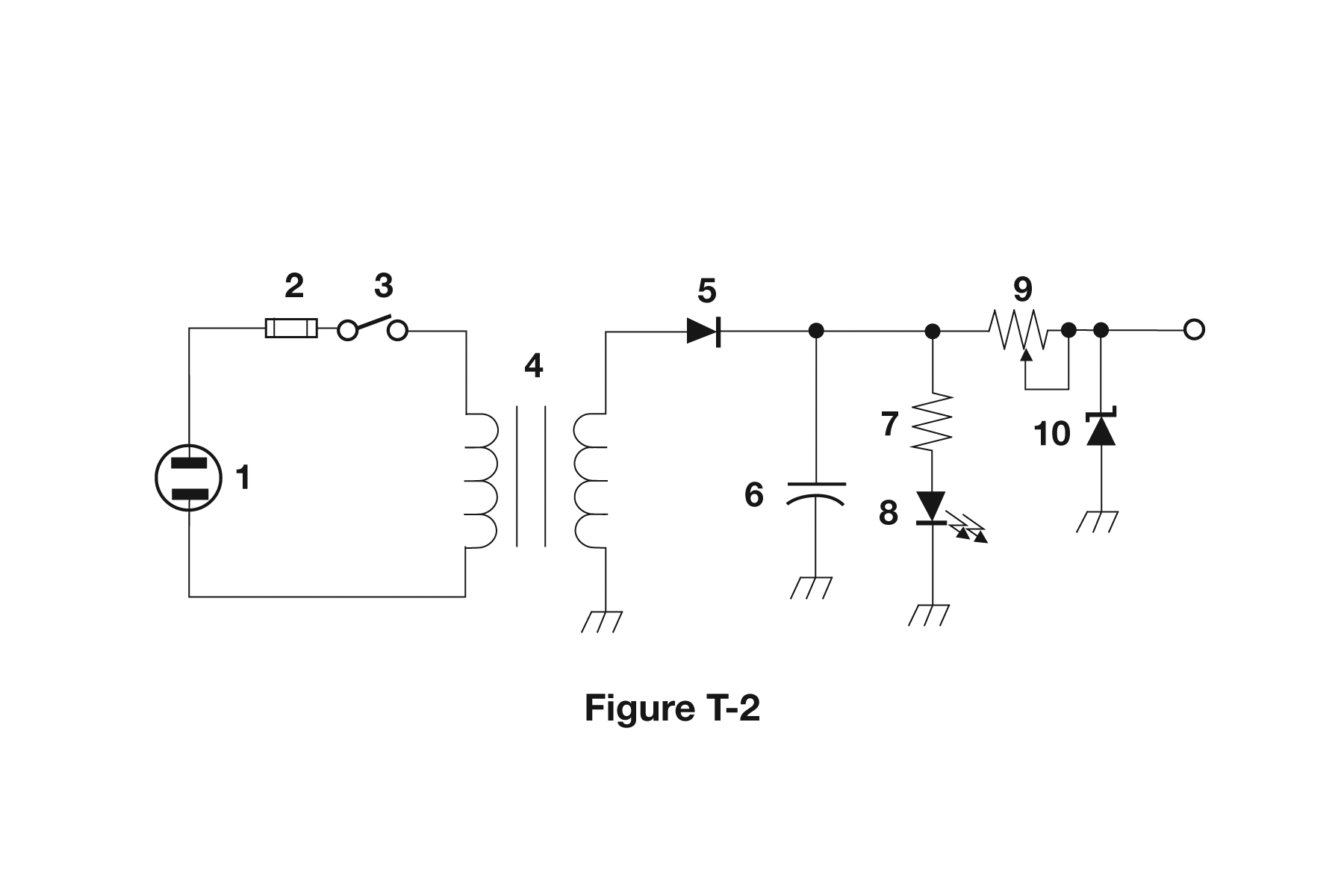
Figure tip: In Figure T-2, component 3 is a Single-Pole Single-Throw (SPST) switch — the simplest kind. It is drawn as a little hinged line that lifts up to open a gap, exactly like flicking a wall switch on and off.
Batteries — which ones can be refilled?
A battery is a tank of stored electrical energy that pushes current out into a circuit. The exam cares about basically one thing here: which batteries can be recharged (refilled with energy and used over and over) versus which ones are one-time-use (you use them up and toss them).
- Rechargeable: nickel-metal hydride (written NiMH), lithium-ion (Li-ion, the kind in your phone), nickel-cadmium (NiCd), and lead-acid (the heavy kind in a car). Because so many kinds can be recharged, the test answer for "which battery chemistry is rechargeable?" is "all these choices are correct."
- NOT rechargeable: carbon-zinc — these are the cheap throwaway dry cells. So the answer to "which battery chemistry is NOT rechargeable?" is carbon-zinc.
Memory hook: if the name sounds fancy or sounds like a car battery, it can usually recharge. Plain old "carbon-zinc" is the toss-it-when-done one.
T6B — Semiconductors: diodes, transistors, and gain
This group is all about parts made from a special material called a semiconductor (say "SEM-ee-con-DUCK-ter"). A semiconductor is a material that sits halfway between a conductor (something that lets electricity flow easily, like copper) and an insulator (something that blocks electricity, like rubber). Because it is "in between," engineers can treat it in clever ways to build parts that steer and control current on command. The two big stars made this way are the diode and the transistor.
Diode — a one-way gate
A diode (say "DIE-ode") is an electric one-way gate, like a turnstile at a stadium that only lets people walk through in one direction. Current can flow forward through a diode just fine, but if it tries to come back the other way, the gate is shut and nothing gets through. So the answer to "what part allows current to flow in only one direction?" is the diode.
A diode has two ends, and the proper word for these ends is electrodes (an "electrode" is just a connection point where current goes in or comes out). The diode's two electrodes are named the anode and the cathode. So the answer to "what are the names for the electrodes of a diode?" is anode and cathode. Current flows in the anode side and out the cathode side. On a real diode you can tell which end is the cathode because it is painted with a stripe — a band printed around the body. So the answer to "how is the cathode lead often marked?" is with a stripe.
When current flows the "open" way through a diode, a small amount of the push (voltage) gets used up crossing the gate. We call this little loss the forward voltage drop. It is completely normal — it does NOT mean the diode is broken — and it is lower in some diode types than in others, because some gate designs are simply easier to push current through than others. That is the answer to the forward-voltage-drop question: it is lower in some diode types than others.
A very common special kind of diode is the LED, which stands for light-emitting diode ("emit" means to give off, so it gives off light). When current flows the correct, forward way through an LED, it lights up and glows. So the answer to "what causes an LED to emit light?" is forward current (not reverse current, and not any kind of RF signal). Because they are small, bright, tough, and last a long time, LEDs are everywhere as little "power on" lights and indicators.
Transistor — a faucet controlled by a tiny finger
A transistor (say "tran-ZIS-ter") is one of the most important inventions in all of electronics. Picture a big water faucet, but instead of a hand turning the handle, a tiny signal turns it. A small input can control a much larger flow of current. That one trick lets a transistor do two amazing jobs:
- It can act as an electronic switch — turning a current fully on or fully off with no moving parts at all (which makes it far faster and far more reliable than a mechanical switch you flip with your finger). So the answer to "which part can be used as an electronic switch?" is the transistor.
- It can act as an amplifier — using a weak signal to control a strong copy of that same signal, making it louder or stronger.
Inside, a transistor is built from three regions of semiconductor material stacked together. So the answer to "which part can consist of three regions of semiconductor material?" is the transistor. There are two main families of transistors, and the easiest way to tell them apart on the test is by the names of their three legs (those electrodes again):
- Bipolar Junction Transistor (BJT): its three legs are named the emitter, base, and collector. A tiny current flowing into the "base" controls a much bigger current flowing between the collector and the emitter. So the answer to "what are the electrodes of a bipolar junction transistor?" is emitter, base, and collector.
- Field-Effect Transistor (FET): its three legs are named the gate, drain, and source. Here a small voltage on the "gate" controls the flow from the drain to the source — like a tiny finger pressing on a hose. So the answer to "what transistor has a gate, drain, and source?" is the field-effect transistor, and the answer to "what does FET stand for?" is Field Effect Transistor.
Quick trick to keep them straight: if you spot the words gate / drain / source, it's a FET. If you spot the words emitter / base / collector, it's a bipolar junction transistor.
Gain — how much bigger the output gets
Gain simply means how much an amplifier boosts a signal: it is the output compared to the input. If you whisper into something and a shout comes out the other side, that's a lot of gain. Gain can describe the boost in voltage, or the boost in current, or the boost in power — so the test answer for "what does gain mean in amplifiers?" is "all these choices are correct."
And the part that can give real power gain — making the output actually carry more power, not just look bigger — is the transistor. So the answer to "which can provide power gain?" is the transistor. Where does the extra power come from? It is not magic and it isn't created from nothing — it is "borrowed" from the radio's power supply, with the small input signal just steering the faucet open and shut. (A transformer can raise a voltage, but it can't give power gain, because it has no power supply of its own to draw extra energy from. More on transformers later.)
T6C — Reading a schematic and knowing the symbols
Now that you have met the parts, let's learn to read the map that shows how they all connect together.
What is a schematic?
A schematic (say "skuh-MAT-ik") is a drawing of a circuit that uses one simple symbol for each part, instead of a photograph. Think of it like a subway map. A subway map does not show the real shape of the trains, the real color of the seats, or how long the tunnels truly are. It only shows which stops connect to which other stops. A schematic works the exact same way: it accurately shows how the components are connected to each other electrically, and nothing more. So the answer to "an electrical diagram using standard component symbols is called…?" is a schematic, and the answer to "what is accurately represented in a schematic?" is the component connections.
Here is the part people miss: a schematic does NOT tell you the real size of the parts, what they look like in real life, or how long the actual wires are. Only the connections are accurate. Two wires that look long on the paper might be tiny in real life, and a part drawn small might really be big. The drawing only promises one thing: it shows you which parts are joined to which. (So when a question lists "wire lengths," "physical appearance," and "component connections," the only correct one is component connections.)
The symbols (these show up in Figures T-1, T-2, and T-3)
The figure questions are friendly: they just point at a numbered symbol and ask "what is it?" Here is a picture-dictionary of the ones you need, with exactly where each one shows up on the exam figures:
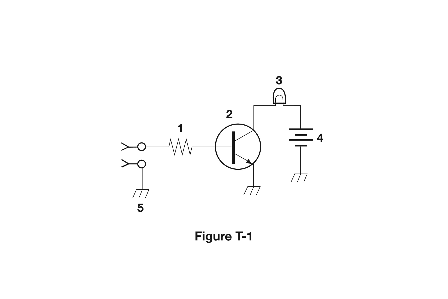
- Resistor — a little zig-zag line (like a saw-tooth), or sometimes a plain rectangle box. In Figure T-1, component 1 is a resistor.
- Transistor — usually a circle with three leads sticking out, and one of those leads has a little arrow on it. In Figure T-1, component 2 is a transistor.
- Lamp — a circle with an X inside it (or a wavy filament line). In Figure T-1, component 3 is a lamp.
- Battery — a stack of alternating long and short parallel lines (the long line is the plus side). In Figure T-1, component 4 is a battery.
- Capacitor — two short parallel lines facing each other (sometimes one of the two is curved). In Figure T-2, component 6 is a capacitor.
- Light-emitting diode (LED) — a diode triangle pointing at a bar, with two tiny arrows pointing away from it (those little arrows are the light shining out). In Figure T-2, component 8 is an LED.
- Variable resistor — a resistor zig-zag with an arrow drawn diagonally through it. In Figure T-2, component 9 is a variable resistor.
- Transformer — two coils drawn side by side, usually with two straight lines between them (those lines stand for the iron core). In Figure T-2, component 4 is a transformer.
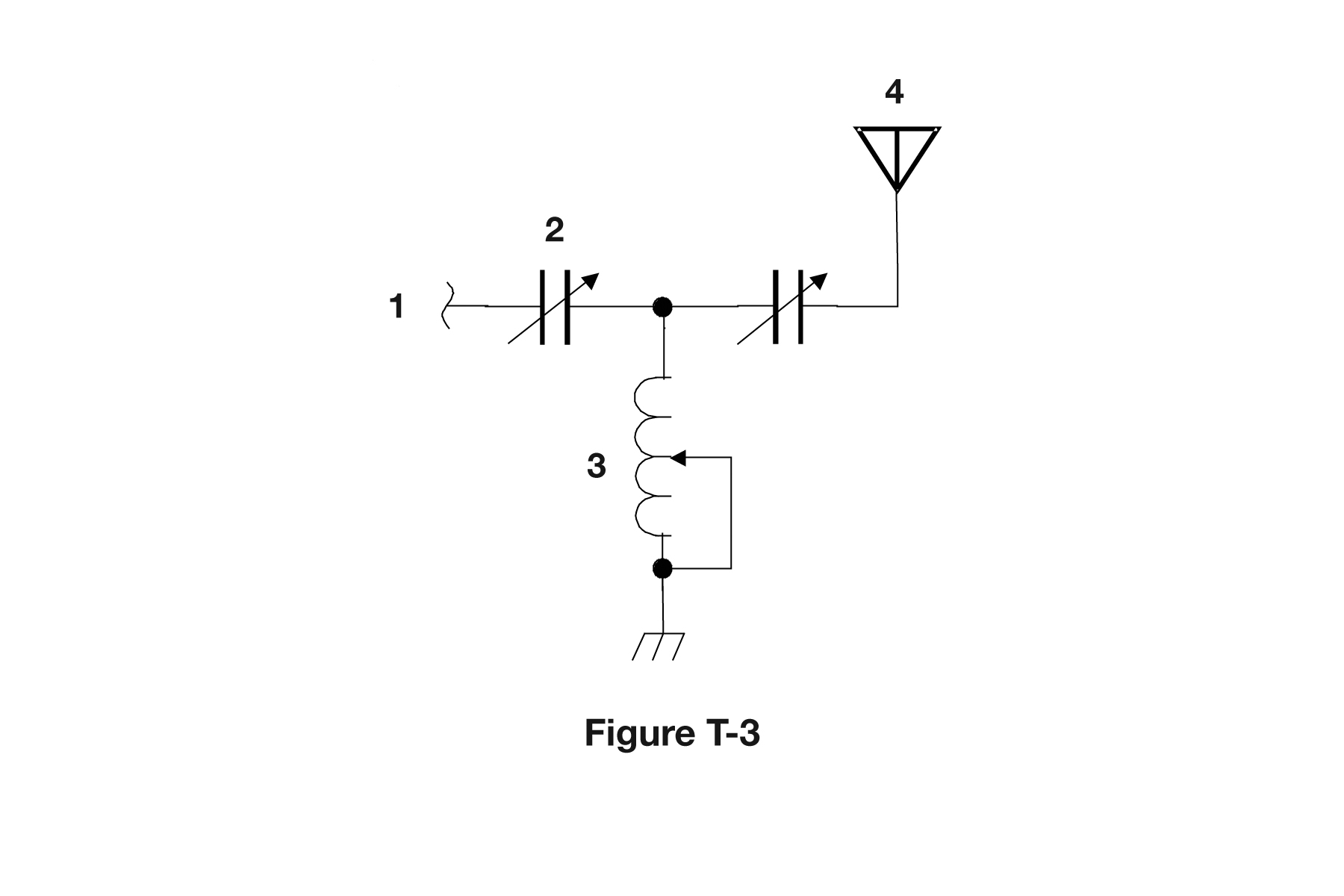
- Variable inductor — a coil (a row of little bumps or loops) with an arrow drawn through it. In Figure T-3, component 3 is a variable inductor.
- Antenna — looks like a "Y" shape, or a stick figure with its arms up. In Figure T-3, component 4 is an antenna.
A few more handy symbols
You'll also bump into these along the way: a plain diode is a triangle pointing into a bar (the bar marks the cathode/stripe side, the same stripe we talked about earlier); a plain inductor is a string of little bumps or loops (the coil of wire); a switch is a hinged line that swings up to open a gap or down to close it; and a ground symbol is a few horizontal lines that get shorter as they go down, marking the circuit's "common return" point (you can think of "ground" as the home base that everything measures from).
The one trick that answers a whole batch of figure questions
Here is the single most useful rule in this lesson: if you see an arrow drawn diagonally through a part, it means that part is VARIABLE (adjustable — you can change it with a knob). An arrow through a resistor means a variable resistor. An arrow through a coil means a variable inductor. An arrow through a capacitor means a variable capacitor. Learn that one rule and several figure questions answer themselves: spot the arrow, then just name what part it is drawn through and add "variable" in front.
T6D — What components do: rectifiers, relays, regulators, transformers, ICs, tuned circuits, shielding
This last group is a "what is this part for?" round. Each part listed here has one clear job. Here they all are, with an everyday comparison for each so the job sticks in your head.
Rectifier — the AC-to-DC traffic cop
First, two words to know. Wall power is AC, which stands for alternating current — it sloshes back and forth many times a second, like ocean tide going in and out. But radios want DC, which stands for direct current — it flows steadily in one direction, like a calm river. A rectifier (say "RECK-tih-fire") is the traffic cop that changes AC into a varying DC by only letting the flow go in one direction. (It is built out of diodes — remember, those are the one-way gates.) So the answer to "which device changes alternating current into a varying direct current?" is the rectifier.
Relay — a switch you flip with electricity
A relay (say "REE-lay") is an electrically-controlled switch. Here's how it works: a small electric current flows through a coil of wire, the coil turns into a magnet, and that magnet yanks a little metal lever that opens or closes a much bigger switch. So a tiny signal can switch a much larger circuit on or off, with no human finger needed — kind of like pressing one little button to make a heavy garage door swing open. So the answer to "what is a relay?" is an electrically-controlled switch.
Voltage regulator — a cruise control for voltage
A power supply's voltage can wobble up and down as the load changes (as parts of the radio draw more or less power), but the sensitive circuits inside a radio want a steady, smooth level to run on. A voltage regulator is the circuit that controls the amount of voltage coming from a power supply, holding the output rock-steady — just like the cruise control in a car holds the speed at one number even on hills. So the answer to "what controls the amount of voltage from a power supply?" is a regulator.
Transformer — gears that trade voltage for current
A transformer (say "trans-FOR-mer") is two coils of wire sharing a magnetic field, and it works like a set of gears for electricity. Just as gears on a bike can trade speed for pulling-strength, a transformer trades voltage for current. It can take in 120-volt AC wall power and change it into a lower (or higher) AC voltage that a device can use. So the answer to "what changes 120 V AC power to a lower AC voltage?" is the transformer. Two important cautions: a transformer works only with AC (it is the changing magnetic field that makes it work, and DC doesn't change), and a transformer never creates extra power — it only trades one thing for another, which is exactly why it can't give "power gain" the way a transistor can.
Meters and indicators — showing you what's happening
A meter displays an electrical quantity as a number (such as showing volts or amps on a screen or a dial). So the answer to "what displays an electrical quantity as a numeric value?" is a meter. And when you just need a simple "is it on?" light, the go-to part is an LED — it's bright, tiny, and lasts a very long time. So the answer to "what is commonly used as a visual indicator?" is an LED.
Integrated circuit (IC) — a whole circuit shrunk onto a chip
An integrated circuit, usually just called an IC or a "chip," packs many semiconductors and other parts into one single tiny package. Imagine taking a whole room full of separate components and shrinking it down to fit on a chip smaller than your fingernail — that's an IC. So the answer to "what is the name of a device that combines several semiconductors and other components into one package?" is an integrated circuit.
Resonant (tuned) circuit — how a radio picks one station
Take a capacitor (our energy bucket) and pair it up with an inductor (our flywheel coil) — wired either in series (one after the other) or in parallel (side by side) — and together they make a resonant circuit, also called a tuned circuit. The two parts trade energy back and forth and "ring" strongly at one special frequency, kind of like how a bell rings at one note. That ringing is exactly how a radio tunes in to one station and ignores all the others. So the answer to "what is combined with an inductor to make a resonant circuit?" is a capacitor, and the answer to "which of these is a resonant or tuned circuit?" is an inductor and a capacitor in series or parallel.
Shielding — a wrapper that blocks noise
Shielded wire is wire that has a metal sleeve wrapped around the inner wire, like a protective sock that blocks radio noise. Why bother? The reason to use shielded wire is to prevent the coupling (the leaking) of unwanted signals to or from the wire. In plain words: it keeps outside interference from sneaking into the wire, and it keeps the wire's own signal from leaking out and bothering other equipment. So the answer to "why use shielded wire?" is exactly that reason — to prevent coupling of unwanted signals to or from the wire.
Figure function question
One exam question asks about the function of component 2 in Figure T-1 — and component 2 is the transistor. Remember our faucet picture: the transistor's job is to control the flow of current. So that is the answer — not "give off light" (that's an LED), not "supply electrical energy" (that's a battery), and not "convert energy into radio waves" (that's an antenna), but control the flow of current.
Common beginner mistakes
- Mixing up capacitor and inductor storage. A capacitor stores energy in an ELECTRIC field; an inductor stores energy in a MAGNETIC field.
- Thinking a potentiometer controls voltage. A potentiometer is a variable resistor, so it controls RESISTANCE (and is often the volume knob).
- Replacing a blown fuse with a bigger one. Always use the same rating — a bigger fuse defeats the protection and can let a fire start.
- Forgetting that carbon-zinc is the throwaway one. NiMH, Li-ion, NiCd, and lead-acid all recharge; carbon-zinc does NOT.
- Assuming a schematic shows real size or wire length. It only shows how the parts CONNECT, just like a subway map.
- Missing the "arrow through a part means variable" rule. An arrow drawn through a resistor, coil, or capacitor marks it as adjustable.
- Mixing up the transistor families. Emitter/base/collector = bipolar junction transistor; gate/drain/source = field-effect transistor (FET).
- Confusing what each part does on a figure: a battery supplies energy, an LED gives off light, an antenna makes radio waves, and the transistor controls the flow of current.
What the exam tests
About 4 of the 35 exam questions come from T6. Many of them are simple "what does this part do?" questions, but several show you Figure T-1, T-2, or T-3 and point at a numbered symbol, asking you to name the part or its job. This course pops the correct figure up right beside each of those questions, so the real skill is recognizing a handful of symbols on sight. The two highest-value things to lock in are (1) every figure answer listed in this lesson, and (2) the "arrow through a part means VARIABLE" rule. Also memorize the matched pairs that the test loves: capacitor = electric field versus inductor = magnetic field, and emitter/base/collector versus gate/drain/source. Do that, and T6 becomes some of the easiest, most reliable points on the whole exam.
Key facts & memory tricks
- Resistor = the "kink in the hose" that opposes/limits current. A variable resistor is a potentiometer ("pot"); it controls RESISTANCE and is often used as a volume control.
- Capacitor = a tiny rechargeable bucket; it stores energy in an ELECTRIC field and is built from two conductive surfaces separated by an insulator.
- Inductor = a flywheel/coil of wire; it stores energy in a MAGNETIC field. Memory: Capacitor = electric field, inductor = magnetic field.
- Switches: poles = how many circuits handled, throws = how many destinations. SPST = plain on/off; SPDT = one circuit switched between one of two other circuits.
- Rechargeable batteries: NiMH, Li-ion, NiCd, and lead-acid ("all these choices are correct"). NOT rechargeable: carbon-zinc.
- Diode = a one-way gate; current flows in only one direction. Its electrodes are the anode and the cathode; the cathode end is marked with a STRIPE.
- An LED emits light from FORWARD current and is commonly used as a visual indicator. Forward voltage drop is normal and is lower in some diode types than others.
- Transistor = a faucet controlled by a small signal; it has three regions of semiconductor. Bipolar electrodes: emitter, base, collector. FET electrodes: gate, drain, source (FET = Field Effect Transistor).
- A transistor can be an electronic switch AND can provide power gain. Gain = output vs input — voltage, current, OR power (all these choices are correct).
- A schematic uses standard symbols and accurately shows only the component CONNECTIONS — not real size, real appearance, or wire length.
- Figure T-1: 1 = resistor, 2 = transistor (its function: control the flow of current), 3 = lamp, 4 = battery.
- Figure T-2: 3 = SPST switch, 4 = transformer, 6 = capacitor, 8 = LED, 9 = variable resistor. Figure T-3: 3 = variable inductor, 4 = antenna.
- One-trick rule: an ARROW drawn diagonally through a symbol means it is VARIABLE (variable resistor / variable inductor / variable capacitor).
- Rectifier: changes AC into a varying DC. Relay: an electrically-controlled switch. Regulator: controls power-supply voltage. Transformer: changes AC voltage (works only on AC).
- Meter: shows a quantity as a number. Integrated circuit: many components in one package. Resonant/tuned circuit: inductor + capacitor (series or parallel). Shielded wire: prevents unwanted signal coupling.
Warm-up questions
Think of your answer, then click to check. These are gentle practice — the real quiz is below.
Easy
Which part slows down or limits the flow of current, like a kink in a hose?
A resistor. Its whole job is to oppose (fight) the flow of current.
What part is built to break on purpose to protect your radio from too much current?
A fuse. A thin sliver of metal inside it melts and opens the circuit if too much current tries to flow.
Which part lets current flow in only one direction, like a one-way gate?
A diode. Current flows forward through it but is blocked going backward.
Which part is basically a coil of wire and stores energy in a magnetic field?
An inductor. Picture a heavy flywheel: it resists sudden changes and holds its energy in the magnetism around the coil.
What is the name for a drawing that uses simple symbols to show how a circuit is connected?
A schematic. It shows the component connections, like a subway map shows which stops connect to which.
A bit harder
A capacitor and an inductor both store energy. What is the difference in HOW they store it?
A capacitor stores energy in an electric field; an inductor stores energy in a magnetic field. Memory hook: Capacitor = electric, inductor = magnetic.
You turn the volume knob on a radio. What kind of part is that, and what does it actually change?
It is a potentiometer, which is a variable resistor. It changes the resistance in the circuit, which adjusts the volume.
On a schematic you see an arrow drawn diagonally through a coil symbol. What does that tell you?
The arrow means the part is variable (adjustable), so it is a variable inductor. An arrow drawn through any part marks it as variable.
A transistor has three legs named gate, drain, and source. What family of transistor is it, and what does the name stand for?
It is a field-effect transistor, abbreviated FET, which stands for Field Effect Transistor. (If the legs were emitter, base, and collector, it would be a bipolar junction transistor instead.)
What two parts do you combine to make a resonant (tuned) circuit, and why does it matter for a radio?
An inductor and a capacitor, wired in series or in parallel. Together they "ring" at one frequency, which is how a radio tunes in to one station and ignores the rest.
Wall outlets give AC, but a radio runs on DC. Which part changes AC into a varying DC, and which part changes 120 V AC down to a lower AC voltage first?
A rectifier changes AC into a varying DC (it is built from diodes, the one-way gates). A transformer changes the 120 V AC into a lower AC voltage, and it works only on AC.
Knowledge check: T6 quiz
Real exam questions for this section, in random order with instant feedback.
Loading quiz…
🃏 Flashcards for this lesson
Every T6 question from the pool as a flip card. Click to reveal the answer, then mark what you know. Saved on this device.
Loading…
🏁 Checkpoint 2 unlocked
You've finished a block of lessons. Take Checkpoint 2 — a cumulative review mixing real questions from every lesson so far. If you miss a topic, it points you straight back to the right lesson.
Take Checkpoint 2 →🛠️ Try it yourself
Try this short activity to make the symbols stick in your memory. Search online for "simple flashlight schematic" or "LED circuit schematic" and open one image. On that image, find and point to three things: a resistor (a zig-zag or a plain rectangle), a capacitor (two short parallel lines facing each other), and a ground symbol (a few horizontal lines that get shorter going down). Next, scroll up to the figures on this page (T-1, T-2, and T-3) and, without peeking at the answers, name each numbered part out loud — say "that's a resistor," "that's a transistor," and so on. Then check yourself against the lesson. As a bonus round, look at any one part with an arrow through it and say "variable!" out loud, then name the part. A few minutes of this beats re-reading the text, because naming symbols on sight is exactly what the figure questions test.
Watch & learn
- Ham Radio Technician License Prep: Sub-Element 6 (2022-2026) — Ham Radio Crash Course (Josh, KI6NAZ)
- Ham Radio Technician License Prep 2022-2026 (full playlist) — Ham Radio Crash Course (Josh, KI6NAZ)
- How to Read a Schematic — SparkFun Electronics